The Making of the Mars Polar Lander Mars Descent Imager (MARDI)

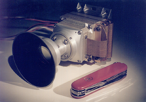
MARDI in the MSSS cleanroom, January 1998.
CLICK HERE
for larger image (1.2 MBytes).
MARDI, not much bigger than a pocket knife,
consists of a stack of circuit boards and aluminum housings
mated with a wide angle lens. The picture above shows the MARDI
flight instrument, just after it was completed at Malin Space Science
Systems (San Diego, California) and just before it was delivered to
Lockheed Martin Astronautics (Denver, Colorado) for integration with
the Mars Polar Lander (MPL) spacecraft.
At the back of the camera (above)
are the mounting feet--these are used to bolt the camera to the spacecraft.
Forward of the feet are a stack of three printed circuit boards, separated
by pieces of aluminum housing and cabled together by means of flexible
printed circuit board cables. The foremost of these three boards connects
by means of another flex cable to a fourth board, the focal plane assembly
(which is not visible). The focal plane board carries an electronically
shuttered charge coupled device (CCD) detector. This CCD converts the
image projected onto it by the lens to an electrical signal. That lens
has a conical sunshade, to prevent direct illumination of the front
element of the lens by the Sun. MARDI interfaces with the spacecraft
by means of two cables, one for power and temperature telemetry, the
other for transfering commands to and data from the camera.

MARDI flight unit data acquisition system
circuit board, October 1997.
The key to reducing the mass and power required for the instrument
was to take advantage of the tremendous advances that have occurred
over the last ten years in electronics. This reduces both the size
and number of electronic components necessary in the design, which
reduces the mass and power required. This picture shows the MARDI
flight data acquisition system (DAS) board. The board is 7 cm (2.75 in)
long and 5.7 cm (2.25 in) wide. The largest component is the digital
signal processor, which controls all instrument functions. The other
components provide the circuitry to transmit to and receive data from
the spacecraft. This and the other MARDI boards were integrated with
the aluminum housing which provides at least 0.15 in. of radiation
shielding.

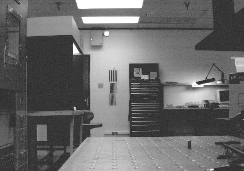
MARDI flight unit focus test, December 1997.
The three rectangles on the wall are bar targets.
The bottom target has a spacing below the Nyquist
frequency of the MARDI detector, so the bars are
aliased to a lower spatial frequency. Note that this
image only covers part of the MARDI field of view.
After integrating the electronics with the housing, the next step
in the MARDI assembly is to mate the electronics with the optics
and then focus the camera. The distance between the lens and CCD
detector is metered by a small spacer ring at the back of the lens.
To focus MARDI, a series of images of a set of bar targets were
acquired with different thickness of shims in place of the focus
spacer ring. The image from the best focus position is shown in
this figure. The test targets are the three vertically stripped
rectangles near the center of the image. The upper two targets
show the system has good contrast down to its limiting resolution.
The bars on the bottom test target are below the size the camera
can resolve at that distance.
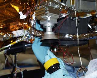
Mars Descent Imager onboard MPL during final cleaning.
Click Here
for "life-size" image (1.3 MByte).
After MARDI was focused, it was put through a series of
environmental and calibration tests before being delivered
for integration with the MPL spacecraft. Environmental tests include
(1) heating and cooling the camera to temperatures it will encounter in space
and on Mars, and (2) shaking the camera to simulate the launch of the MPL
spacecraft. Once delivered to Lockheed Martin Astronautics in
Denver, Colorado, the instrument was bolted to the lower side of the
spacecraft, as shown here. At this location on the MPL lander, the camera
will be able to "see" the landing site during descent.
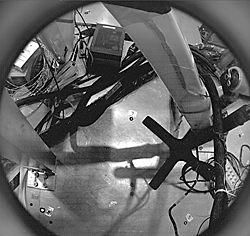
MARDI picture taken after integration with the spacecraft
at Lockheed Martin Astronautics. MARDI is looking at the floor.
The location of test points, numbered one through five, were
determined
by theodolite.
Click Here for higher-resolution
view (575 Kbytes).
After MARDI was integrated with the spacecraft, it was necessary
to measure where it was pointed relative to the spacecraft. Five
precision measured test points were surveyed in on the floor beneath
the spacecraft, within the MARDI field of view. MARDI took an image
of those points, which are seen numbered in the picture above. Knowing
were the points are relative to the lander and in the MARDI image will
allow location of surface features on Mars in MARDI images relative to
the lander.
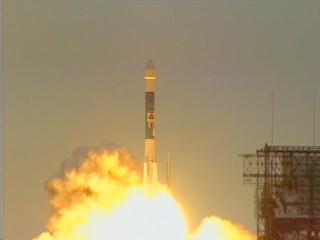
MARDI was aboard when MPL was launched January 3, 1999.
The Mars Polar Lander, with MARDI aboard, was launched from
Florida on January 3, 1999. The scheduled date for MARDI's
entire mission--to acquire images of the landing site during
terminal descent of the Mars Polar Lander--is December 3, 1999.
For questions or comments on this website please refer to our list of contacts.
©1999 Malin Space Science Systems, Inc.